|
Product Overview
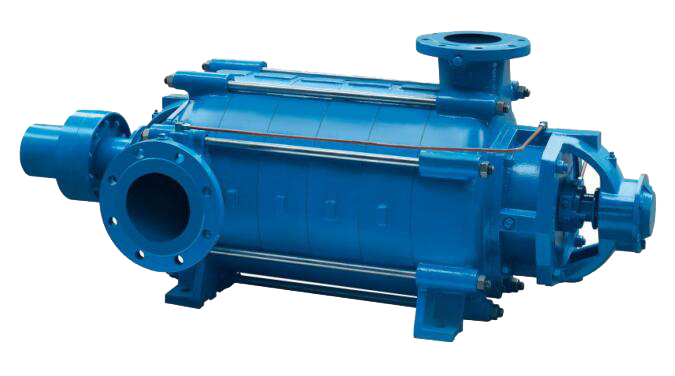
The KDW series multi - stage pumps
are the latest generation of multi -
stage pump products newly developed
and designed by Jiangsu Kaifeng Pump
& Valve Co., Ltd. Their excellent
hydraulic performance and structural
features ensure that users can
effectively reduce the operating
costs of the pumps in various
application scenarios.
Technical Parameters
Pump Port Diameter:
Suction 40 - 250mm, Discharge 25 -
200mm
Flow Rate: Up to
500m³/h maximum
Liquid Temperature:
Maximum ≤80 ℃
Head: Up to 360m
maximum
Direction of Rotation:
When viewed from the motor side, the
impeller rotates clockwise
Shell Pressure: Up to
4.0MPa maximum
Product Standard: Q/FP
2104 Centrifugal Pumps for General
Purposes
(Shell Pressure - Bearing Capacity =
Inlet Pressure + Shut - off Head)
Shaft Seal Type: Packing
Seal or Mechanical Seal
Application Fields
The KDW series multi - stage
centrifugal pumps are mainly used
for pumping clean water and liquids
containing trace impurities with
physical and chemical properties
similar to water. They can be widely
applied in the following fields:
paper mills, waterworks or water
supply companies, liquid booster
devices, circulation and cooling
systems, fire protection,
refineries, water conservancy
irrigation, high - pressure water
stations, etc.
Product
Features
This type of pump is a multi - stage
centrifugal pump with segmented,
horizontal, and closed impellers,
including 10 size specifications.
Each specification has 2 to a
maximum of 10 impeller stages, and
it adopts a unique axial force
balancing mechanism: a combination
of balancing holes (double - seal
rings), labyrinth - type throttling
sleeves, and pressure - relief
pipes. The residual axial force is
borne by a set of angular contact
ball bearings.
Each type of pump can be equipped
with impellers of different
diameters, meeting users' diverse
performance requirements and
reducing power loss.
For pumps with specifications KDW25
- KDW80, the pump feet on the
suction section side are located on
the first - stage intermediate
section, and the suction port
direction can be adjusted
appropriately to adapt to different
installation conditions.
The drive end is located on the
suction section side of the pump.
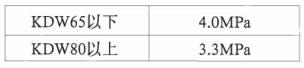
Shell pressure -
bearing capacity:
The Relationship Between Pump
Dimension Specifications and
Pressure Bearing Capacity of Casing
Components
Nozzle
Position:
When viewed from the motor end, the
pump's suction port faces
horizontally to the right, and the
discharge port faces vertically
upward. For pumps in the KDW25 -
KDW80 specifications, the suction
port direction can be adjusted to
the left according to the user's
pipeline layout. When the number of
stages is three or more, the suction
port can also be positioned
vertically upward (please specify
these requirements when placing your
order).
Flanges:
The inlet and outlet flanges comply
with the standard: GB/T 17241.6 -
1998 neq ISO 7005.2:1988. The
applicable nominal pressure ratings
for the flanges are as follows:
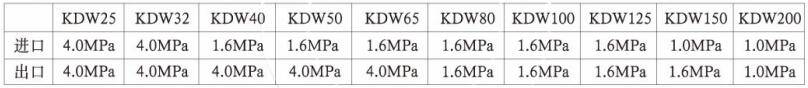
Note:
The inlet flange is of a larger
diameter, while the outlet flange is
of a smaller diameter. For the same
nominal diameter, the flange
dimensions for a nominal pressure of
4.0MPa are also applicable to those
for nominal pressures of 1.0MPa,
1.6MPa, and 2.5MPa.
Bearings:
The standard configuration is NSK -
brand bearings. The suction end
adopts cylindrical roller bearings,
and the discharge end uses angular
contact ball bearings. The bearings
are filled with No. 3 complex
lithium - based grease before
leaving the factory.
Shaft Seals:
According to the usage requirements,
the shaft seal can be either a
packing seal or a mechanical seal.
The mechanical seal is the standard
configuration. The installation
dimensions of this series of
mechanical seals comply with the
DIN24960 standard, and the CRANE2100
- type mechanical seal is selected.
Sealing Rings:
All the sealing rings are made of
fluoro - rubber (FPM).
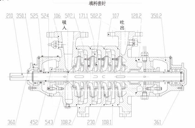
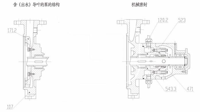
Schematic Diagram of the Pump:
|
106-Suction
Section |
107-Discharge
Section |
108.1-Intermediate
Section |
108.2-Intermediate
Section |
|
120.1-Additional
Section |
120.2-Additional
Section |
171.1-Radial
Guide Vane |
171.2-Radial
Guide Vane |
|
210-Shaft |
230-叶轮Impeller |
350.1-Bearing
Housing |
350.2-Bearing
Housing |
|
360-Bearing
Cover |
361-Bearing
End Cap |
452-Packing
Gland |
457-Packing
Spacer Ring |
|
471-Mechanical
Seal Gland |
502.1-Sealing
Ring |
502.2-Sealing
Ring |
523-Mechanical
Seal Sleeve |
|
524-Packing
Sleeve |
525-Spacer
Sleeve |
543.1-Spacer |
543.3-Spacer |
|